Automatic battery charger
SPQ-2400 AUTOMATIC BATTERY CHARGER
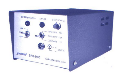
General description
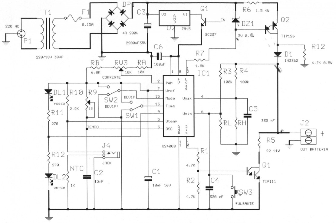
The SPQ-2400 is a battery charger for Ni-Cd / Ni-Mh elements with fully automatic pre-charge and charge phase. An electronic switching circuit recognizes four types of batteries: 4.8 / 7.2 / 9.6 / 12 V, i.e. 4, 6, 8, and 10 cells in series, suitably adjusting the end-of-discharge voltage thresholds and end of charge. It is possible to select two different types of charge:
fast charge with constant current, programming the times of 1/2 hour or 1 hour;
slow charge with impulse current, choosing the time of 12 hours.
To recharge a Ni-Cd battery it is sufficient to set the charging time with the SW1 switch and then, connect the accumulator to the output, placing the NTC temperature sensor in contact with it, if used. After about 1 second the red LED DL1 will start to flash indicating that the pre-discharge phase is in progress, which can be interrupted by pressing the SW3 button, in the case of using batteries without memory effect, such as those at NI-MH. Once the pre-charging phase is completed, the charging phase will be activated, signaled by the flashing green LED DL2. The state of end of charge is obtained in the following cases:
reaching the time programmed by SW1. In this case, the regular charge ends, highlighted by the steady lighting of the green LED DL2 and the subsequent passage to maintenance charge.
exceeding the maximum voltage threshold (1.8 V / el.) If this occurs before the predetermined time has elapsed, there are 2 possibilities: with SW2 on ON, the charge is interrupted and the red LED DL1 remains active; if instead SW2 is OFF, charging continues until the preset time is reached, and the anomalous situation is signaled by the alternating flashing of the 2 LEDs.
exceeding the maximum temperature threshold Also in this case there is an interruption of the charge regardless of the elapsed time; the function of SW2 is still the one described above.
Controls and adjustments
DL1 - This flashing red LED diode on indicates that the pre-discharge phase is in progress; steady on indicates that the charging phase has been interrupted due to exceeding the voltage or maximum temperature thresholds.
DL2 - Green LED diode which, if on and flashing, indicates that charging is in progress; if it is steady on, it indicates that the charging phase has been completed regularly and that the maintenance charge has been passed.
SW3 - Button that allows you to interrupt the pre-discharge phase at any time; it is useful if you connect a battery that does not have a memory effect or has a different voltage than the expected ones.
SW2 - 2-position diverter which, if set to ON, enables the interruption of the charge in the event of an anomaly (exceeding maximum thresholds or damage to the battery); in the OFF position, the interruption is disabled, even though the anomalous condition is signaled by alternating flashing of DL1 and DL2.
SW1 - 3-position diverter that allows you to select the charging time: 30 or 60 minutes for a charge with constant current (fast charge), or 12 hours for an impulse current charge; this last type of charge favors the useful life of the battery avoiding the deterioration of the electrodes and overheating.
J2 - Output connector; there is a protection against short-circuits and polarity inversions; with no load, that is with the battery disconnected, there is no voltage at the output.
Automatic switch
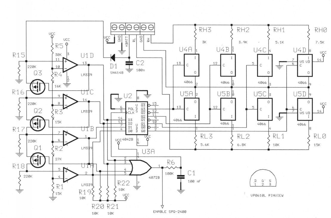
The operating principle of the automatic threshold switch is based on the possibility of discriminating 4 different types of battery, consisting of 4, 6, 8 or 10 cells of 1.2 V in series, associating the voltages supplied to one of the 4 ranges of a multiple window comparator; the hypothesis for the correct recognition of the battery is that the no-load voltage is between 1.1 and 1.4 V per element, conservative values compared to those measurable on non-defective cells, respectively completely discharged or fully charged, obviously not connected to loads or generators. In the case of defective cells or which in any case have voltage values below 1.1 V / element, it will be necessary to carry out a first charge cycle by excluding the discharge phase by means of SW3, to bring the battery back within the normal minimum operating voltage values. .
Current adjustment
The amplitude of the output current, set at 0.8 A during testing, is adjustable with the RV3 trimmer from 0 to 1 A; turning it counterclockwise increases the amplitude of the current. This regulation acts on all the charge regimes (constant, impulsive, maintenance) and on the discharge.
Timer adjustment
Variations of +/- 50% with respect to the nominal values are possible (0.5 / 1/12 h) by acting on the resistive trimmer R9; turning it counterclockwise increases the period. During the testing phase, R9 is regulated in such a way as to have actual times 20% higher than the nominal ones, considering the average efficiency of the charge cycle and therefore allow the complete recharge of the 800 mAh cells. To load cells with a lower capacity, SW2 must be set to ON; in this way the charge will be interrupted when the maximum end-of-charge voltage (1.8 V / cell) or the maximum temperature (45 ° C) is reached.
Technical features
- Power supply: 220 Vac 50 Hz 30 VA
- Mains fuse: 250 mA 5x20 (T) on the board
- Timer: 3 selectable intervals: 0.5 / 1/12 hours
- Preload: automatic, with the possibility of manual interruption
- End of discharge threshold: 1 V per element
- End of charge threshold: 1.8 V per element
- Temperature threshold: 45 ° C
- Current supplied: 0.8 A constant or impulsive
- Maintenance: 0.8 A impulsive
- Discharge current: V batt / 22 [A] (maximum)
- Battery monitor: activated by battery voltages greater than or equal to 3 V.
- Protections: against polarity inversions and / or battery anomalies.
- Dimensions: 179 x 97 x 74 mm
- Weight: 1,5 Kg