
Winding machine with Z80
AUTOMATION WINDING MACHINE WITH MICRO-PROCESSOR SPQ-Z80
1 General description
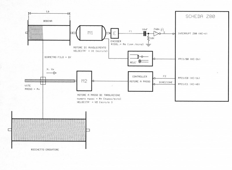
The implementation of an automation system for a winding machine is analyzed below. An SPQ-Z80 microprocessor, using the signal provided by an angular microencoder integral with the rotation axis of the winding motor (see figure 1), generates the control pulses for the stepper motor M2 which in turn controls the wire guide mounted on the nut.
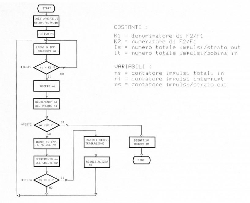
The control program consists of a main module in Basic whose task is mainly to perform the calculation of the various numerical constants used by the subroutines in Assembler. In order to synchronize the translation of the nut screw operated by the stepper motor M2 with the rotation speed of the motor M1, the Assembler program generates a control frequency (F2) proportional and "linked" to that generated by the encoder (F1), controlling also the inversion of the direction of translation upon completion of each layer, and the stopping of the winding motor upon reaching the desired number of turns. The constants used by the Assembler program that must be calculated by the Basic program based on the data provided by the user and the physical parameters of the machine are the following:
K1, K2 = respectively denominator and numerator of the fraction F2 / F1 reduced to the minimum terms.
Is = number of pulses sent to the stepping motor necessary to complete the translation relative to each layer.
It = total number of pulses sent by the encoder corresponding to the number of rotations of the M1 motor to complete the winding.
In the following, the above parameters are analyzed from a physical point of view in order to establish the limits of the acceptable values and the calculation formulas to be used with the Basic program.
1.0 Project data
- Motor M1: speed = V1 [rpm]
- M2 motor: speed = V2 [rpm]
- Motor M2: n ° steps = Pp [steps / revolution]
- Encoder E: resolution = Ig [imp./giro]
- Screw V: pitch = Pv [mm / rev]
- Copper wire: diameter = Df [mm]
- Coil: length = Lb [mm]
- Coil: total number of turns = Ns
2.0 Limits of operation
To limit the maximum alignment error of the lead screw-wire guide to the profile of the layer of the coil being wound, the minimum possible translation of the guide, deltax, corresponding to a single pitch of the M2 motor, must be less than the diameter of the smallest usable wire Dfmin . This condition determines the upper limit of the pitch of the screw Pv, (assuming that the resisting friction force in relation to the driving force of translation linked to the torque of the stepping motor is negligible).

 (1)
(1)The lower limit of the pitch of the screw Pv is determined by the maximum translation speed of the lead screw Vx required, which in turn is linked to the speed of the winding motor M1 and to the diameter of the wire with the largest useful diameter Dfmax. On the other hand, Vx is limited by the maximum rotation speed of the stepper motor V2max; translating into formulas:
Vx = V1 Df; (travel speed impressed by M1) (2)
Vx = V2 Pv; (travel speed impressed by M2) (3)
equating (2) to (3) we obtain the condition:
V1 Df
Pv = ------------- (4)
V2
using the maximum values for the wire diameter and for the motor speeds, the lower limit of the screw pitch is obtained:
V1max Dfmax
Pvmin >= ------------------------ (5)
V2max
The screw pitch must therefore be included between the two limits given by (1) and (5).
Example 1:
Given the following values:
V1 = 50 [rev / s]; V2max = 2.5 [rev / s]; Dfmin = 0.1 [mm];
Dfmax = 0.5 [mm] Pp = 200 [steps / revolution];
derive the range of acceptable values for Pv.
from (1) we obtain:
Pvmax <= 0.1 X 200 = 20 [mm]
and from (5) we get:
50 X 0,5E-3
Pvmin >= -------------------- = 10 [mm]
2,5
In this case, the pitch of the screw must therefore have a value between 10 and 20 mm.
3.0 Control algorithm
The condition of synchronism between the lead screw-wire guide and the coil being wound is achieved by means of the microprocessor control circuit, which must control the motor M2 with a frequency F2 proportional to the frequency F1 generated by the encoder E. The main program in Basic carries out the calculations of the operating parameters used by the assembler routine to generate the command pulses.
F1 = V1 Ig; (frequency generated by the encoder) (6)
F2 = V2 Pp; (frequency sent to the stepping motor) (7)
by imposing the condition of synchronism, that is that the translation speed x impressed by the winding motor is equal to that impressed on the guide by the step motor and that is by equating (2) with (3) we obtain:
V1 Df = V2 Pv (8)
V1 Df
V2 = ------------- (9)
Pv
expressing V1 and V2 as a function of F1 and F2 by means of (6), (7) we obtain:
F2 Pp Df
------ = ------------- (10)
F1 Ig Pv
The (10) represents the system synchronism equation and must be calculated numerically by the Basic module of the control program, in order to provide the Assembler program with the necessary integer constants. In (10), the constants Pp, Ig, Pv are determined a priori and depend on the characteristics of the electromechanical components used, Df is introduced by the user while the frequency F1 is detected (interrupt) by the encoder.
Example 3:
Given the following numerical values:
Pp = 200 [steps / rev], Df = 0.25 [mm], Ig = 5 [imp./ revolution], Pv = 6 [mm]:
calculate the ratio F2 / F1.
F2 200 X 0,25 E-3
----- = ------------------------ = 1,6 (period 6) ;
F1 5 X 6E -3
since, as we have already observed, the assembler program requires integer constants, the ratio F2 / F1 must be expressed in fractional form to obtain the constants K2 and K1. In this case it is easy to get:
5
1,6(period 6) = ------
3
the two desired constants have therefore been obtained: K2 = 5; K1 = 3;
since the pairs of useful values K1 and K2 are limited in number (equal to the number of wire diameters Df used), it is convenient to calculate them all and store them in the form of a program table.
3.1 Reel length
The program must generate pulses with a frequency given by (10), inverting the direction of translation when reaching the edge of the coil.A further data entered by the user is therefore the length of the coil which determines the total number of Is pulses for each layer By equating the length of the coil Lb to the translation of the lead screw Pv due to the number of pulses Is sent to the stepping motor, we obtain:
Is
Lb = --------- Pv ; ( with Is / Pp = total number of M2 revolutions)
Pp
therefore we obtain for Is:
Pp
Is = -------- Lb (12)
Pv
The (12) provides the total number of pulses per layer that the assembler routine must send to the stepping motor M2, as a function of the length of the coil Lb, introduced by the user at the beginning. This formula must also be calculated numerically by the Basic program.
3.2 Total number of turns
Given the total number of turns Ns, the corresponding total number of It pulses sent by the encoder is given by:
It = Ns Ig (13)
3.3 Constants K1, K2
The constants K1 and K2, used by the Assembler program to calculate the proportion between the frequency F2 command pulses of the M2 motor and that of the encoder F1 output must be calculated numerically by making the ratio F2 / F1; reduced to a minimum the fraction, we define K2 equal to the numerator and K1 equal to the denominator.
Example 4:
F2
Obtain the ratio ------ for the standard values of the copper wire diameter.
F1
Df1 = 0.05 mm Df1 = 0.08 mm; Df2 = 0.1 mm Df3 = 0.12 mm
Df4 = 0.15 mm Df5 = 0.18 mm; Df6 = 0.2 mm Df7 = 0.224 mm
Df8 = 0.25 mm Df9 = 0.315 mm Df10 = 0.4 mm Df11 = 0.5 mm
Df12 = 0.56mm Df13 = 0.71mm Df14 = 0.8mm Df15 = 1.0mm
rewriting (10), with Pp = 200 steps / revolution, Ig = 5 pulses / revolution, and Pv = 6 mm, we obtain:
F2 Pp Df
----- = -----------
F1 Ig Pv
F2a 200 X 0,05E-3 1
------ = ------------------------- = -------- ; K2 = 1 ; K1 = 3 ;
F1a 5X6E-3 3
F2b 8
------ = 6666,7 X 0,08E-3 = -------; K2 = 8 ; K1 = 15 ;
F1b 15
F2c 2
------ = 6666,7 X 0,1E-3 = ------- ; K2 = 2 ; K1 = 3 ;
F1c 3
F2d 4
------ = 6666,7 X 0,12E-3 = ------ ; K2 = 4 ; K1 = 5 ;
F1d 5
F2e
------ = 6666,7 X 0,15E-3 = 1 ; K2 = 1 ; K1 = 1 ;
F1e
F2f 6
------ = 6666,7 X 0,18E-3 = ------ ; K2= 6 ; K1 = 5 ;
F1f 5
F2g 4
------ = 6666,7 X 0,2E-3 = ------- ; K2 = 4 ; K1 = 3 ;
F1g 3
F2h 3
------ = 6666,7 X 0,224E-3 = ------ ; K2 = 3 ; K1 = 2 ; (e=+0,45%)
F1h 2
F2i 5
------ = 6666,7 X 0,25E-3 = ------ ; K2 = 5 ; K1 = 3 ;
F1i 3
F2l 21
------ = 6666,7 X 0,315E-3 = ----- ; K2 = 21 ; K1 = 10 ;
F1l 10
F2m 8
------- = 6666,7 X 0,4E-3 = ------- ; K2 = 8 ; K1 = 3 ;
F1m 3
F2n 10
------ = 6666,7 X 0,5E-3 = ------- ; K2 = 10 ; K1 = 3 ;
F1n 3
F2o 15
------ = 6666,7 X 0,56E-3 = ------- ; K2 = 15 ; K1 = 4 ;
F1o 4
Example 5:
with Pp = 200 [steps / rev], L = 40 [mm], Pv = 6 [mm / rev]
Ig = 5 [steps / revolution], Df = 0.3 [mm], F1 = 250 Hz
200 X 40E-3
Is = ------------------------- = 1333,3 pulses ;
6E-3
Indirizzo HEX | Peso cifra | ||
| K1 | denominator of F2 / F1 | FC00H | |
| K2 | numerator of F2 / F1 | FC01H | |
| IS | total number of pulses / input layer | FC02H | X1 |
| FC03H | X10 | ||
| FC04H | X100 | ||
| FC05H | X1000 | ||
| FC06H | X10000 | ||
| IT | total number of pulses / input coil | FC07H | X1 |
| FC08H | X10 | ||
| FC09H | X100 | ||
| FC0AH | X1000 | ||
| FC0BH | X10000 | ||
| ns | number of pulses / output layer | FC0CH | X1 |
| FC0DH | X10 | ||
| FCOEH | X100 | ||
| FC0FH | X1000 | ||
| FC10H | X10000 | ||
| FC11H | flag | ||
| ng | number of input impulses / revolution | FC12H | X1 |
| FC13H | X10 | ||
| FC14H | X100 | ||
| FC15H | X1000 | ||
| FC16H | X10000 | ||
| FC17H | flag | ||
| ni | number of interrupt pulses | FC18H | |
| dm | motor direction | FC19H |