SCADA for aqueduct
SCADA CONTROL SYSTEM FOR MUNICIPAL AQUEDUCT
These notes refer to a control and supervision system created by ELCOSYS at the Municipal Aqueduct of Ghemme, in the province of Novara, which manages the water distribution for over 4000 users. The system was installed in 2004 and is still fully operational. The heart of the system consists of a SCADA application designed by Elcosys in the DAQFactory development environment that acquires in real time the water level of the water tanks, the flow rate of the adduction pumps and the water pressure in the network and, in relation to acquired values controls the four medium power pumping stations (from 15 to 40 kW). The DAQFactory program manages the acquired data in real time and provides for the activation and regulation of the flow rate of the pumping stations and the valves of the network communicating with the remote control units. (RCU) All the photos were taken during the installation and operational testing phases of the system.
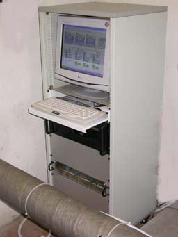
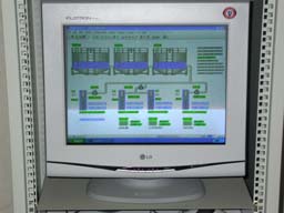
Fig. 1 - SCADA Main Control Center Workstation consisting of: industrial PC in 4U x 450 rack drawer with PENTIUM IV 2.4 GHz, 512 MB RAM DDR, 200GB Hard Disk, 8-port multiserial card, extended keyboard and optical mouse, CDROM / WR and floppy - Analog acquisition module, digital I / O / relay + 3 leased-line MODEM in 2U rack drawer - 500 W UPS in 2U rack drawer - 17 "flat color monitor - keyboard and mouse - SCADA software.- Assembled in 19 "28U x 455 rack cabinet.
The main function performed by the system is to control the operation of 6 pumping stations connected to 3 reserve water basins. Data from pumping stations, reservoirs and pressure points are measured and continuously transmitted to the control center. Fig. 1 shows the SCADA industrial workstation, which implements the system control center by acquiring the pump flow rate data and the water level and controlling the activation of the pumps in the remote stations, in order to keep constant the level in the reservoirs. The SCADA control unit also carries out the collection, graphic display and archiving of all the collected data and allows the setting of all the system setup parameters. The pumping stations and water basins are located in an area of about 3 km radius from the control center, therefore the system is connected to the local network via MODEM for dedicated lines that guarantee the connection of the workstation with the remote control units. The system also allows remote connection via MODEM and / or internet by external technicians who, via PC, can download the desired data and upload any new setup parameters.
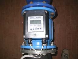
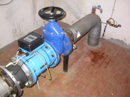
Fig. 2 PUMPING STATION 1 Electromagnetic flowmeter with signal converter and display mounted on DN150 pipe connected to a 15 kW submersible lifting pump.
Fig. 2 shows an electromagnetic flow meter installed in pumping station No. 1, (10 m from the control center) for measuring the flow rate of a submersible pump group. The acquired data is sent via shielded cable to the analog acquisition module of the SCADA Workstation.

Fig. 3 PUMPING STATION 2 Electric control cabinets for 30 kW pump group and IDROLOG80 control unit
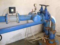
Fig. 4 PUMPING STATION 2 Electromagnetic flowmeter with signal converter and display
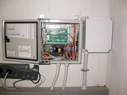
Fig. Fig. 5 PUMPING STATION 2 RCU IDROLOG80 remote pumping station acquisition / control.
Fig. 3 and 4 refer to pumping station N.2 (3 km from the control center); the data acquired by the IDROLOG 80 control unit are transmitted via MODEM on a dedicated TELECOM line to the SCADA control unit.
In fig. 5 you can see the IDROLOG80 remote control unit, assembled in an IP55 cabinet, equipped with a microprocessor with 16-channel analog acquisition, a relay card with 8 outputs and a MODEM for a dedicated line; the control unit works in slave mode, controlled by the control unit SCADA program; sends the acquired data and controls the pumps in well 2.
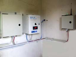
Fig. 6 WATER BASIN STATION IDROLOG80 control unit, water level meter and GSM remote alarm for emergency levels.
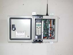
Fig. 7 WATER BASIN STATION GSM remote alarm with 5 inputs with double voice message and 2 relays for remote activation
Figs. 6 and 7 illustrate the interior of the remote control station of the three reserve water basins of 300 cubic meters each, located on a hill about 50 m above sea level. An IDROLOG80 control unit acquires the pressure and water level data from the transducers, displayed locally on a LED display and transmits them to the control center via the MODEM leased-line. There is also a GSM remote alarm, (Fig. 6) to transmit any alarm messages of exceeding thresholds (min or max) in real time to the aqueduct surveillance technicians.
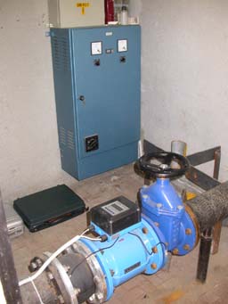
Fig. 8 PUMPING STATION 3 Electric control cabinet for 40 kW pump group and flow meter
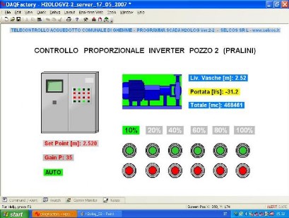
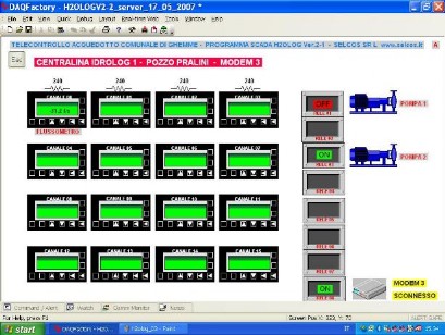
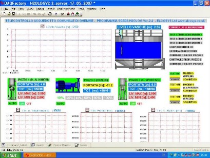
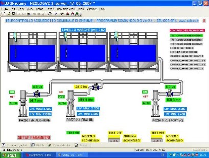
Fig. 8 documents the set point setting and calibration phase of the flow meter of the pump group of station No. 3, about 3 km from the SCADA control center. The system described is fully remotely manageable, by means of a remote PC connected to the SCADA control unit via modem; it is possible to download real-time and historical archived data and it is possible to carry out remote activations and tests of the controlled equipment. Below are some screenshots of the SCADA Main Station during plant operation.