Remote control for telephone line
DTMF Remote control for land-line
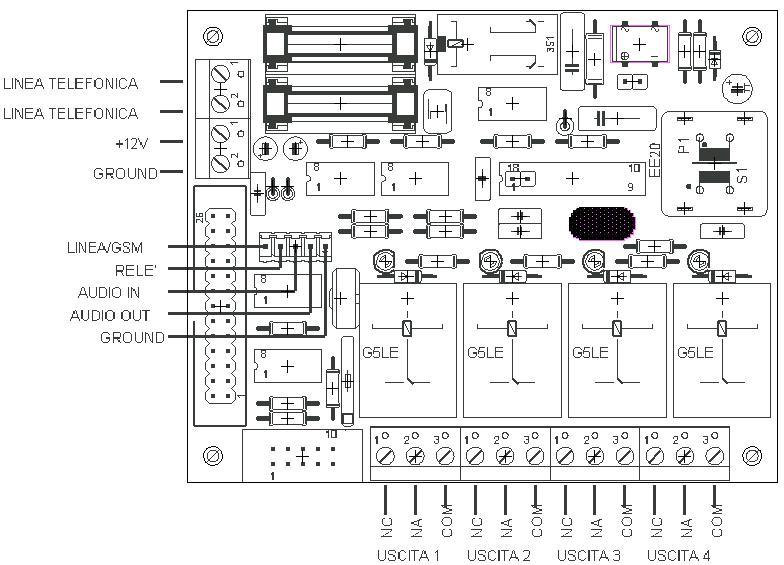
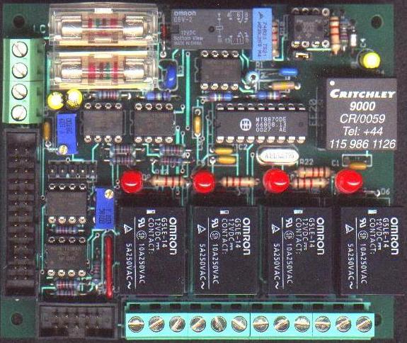
The TELCO-DTMF remote control, consisting of two 1/2 Eurocard format cards (100x80 mm) interconnected by a 26-pole flat cable, is managed by the Z8S180 microprocessor, and carries out the function of controlling 4 power relays (220V 10A) via the telephone line , using for remote activation a telephone with a DTMF keypad or a traditional telephone and a separate DTMF tone generator, of the type used for telephone answering machines. As an alternative to the fixed telephone line, it is possible to use a GSM mobile phone of any type, which has the automatic answer function, connected via the headset microphone socket to the 5-pole connector of the card. More generally, it is possible to connect to the TELCO-DTMF audio line any telecommunication device (radio transceiver, intercom ... etc.) that has an audio input and output. It is also possible to read the status of the 4 power outputs as well as that of the 3 auxiliary inputs, to carry out checks on the status (ON, OFF) of the relays and checks on any sensors located in the remote environment. All the controls have an acoustic feedback that uses 5 different tone sequences.
The output relays are of the single-pole 2-way switch type and therefore have 3 contacts each: common (COM), normally open (NO) and normally closed (NC), which are brought back to the 12-pole terminal block accessible inside the cabinet, after removing the cover by unscrewing the 4 fixing screws of the feet.
The activation status of the 4 relays is stored on NVRAM and therefore, in the event of a mains voltage failure, when the mains voltage returns, the same status of the relays existing before the black-out is restored.
To use the device connected to the telephone line, it is necessary to carry out the following operations:
1 - Connect the remote control to the telephone line and to a stabilized 12VDC 500 mA power supply; for connections, refer to the attached diagram. By activating the power supply, after carrying out a short self-diagnosis program, the remote control goes into the call waiting state; from GSM if connected, or from a telephone line.
2 - Dial the number of the user whose line the remote control is connected to.
3 - After 4 rings the connection is activated and a message (5 tones) of connection to the line is received, or in the case of reception from GSM, an impulsive signal is heard immediately after connection, with a period of about 1 s, which indicates waiting for the password to be received.
4 - Enter the password, consisting of 5 digits.
5 - A message (4 tones) is issued to confirm the correct reception of the password; if, on the other hand, an incorrect digit is entered, an error signal is emitted (4 short beeps), and the password must be re-entered starting from the first digit.
In the fixed line reception mode, If the password is not entered correctly within 30 seconds, the remote control, after having scanned the last 10 seconds available with short beeps and transmitting an acoustic signal, automatically disconnects from the line and goes on hold. of a new call
6 - If the password has been received correctly, it is possible to type 12 different commands; the 4 relay activation commands work in set-reset mode, ie the repetition of the command alternates between the on and off status. The audible message confirming the execution of the command consists of a sequence of two separate tones of a musical octave: low-high = on, high-low = off.
7 - At the end of the command sending phase, it is necessary to type # to terminate the connection and set up the remote control in the ST-BY phase.
The commands are associated with the characters of the telephone keypad as follows:
1 = Activation of output 1 with acoustic confirmation (low-high = ON, high-low = OFF)
2 = Activation of output 2 with acoustic confirmation (low-high = ON, high-low = OFF)
3 = Activation of output 3 with acoustic confirmation (low-high = ON, high-low = OFF)
4 = Activation of output 4 with acoustic confirmation (low-high = ON, high-low = OFF)
5 = Reading of output 1 status (low-high = ON, high-low = OFF)
6 = Reading of output 2 status (low-high = ON, high-low = OFF)
7 = Reading of output 3 status (low-high = ON, high-low = OFF)
8 = Reading of output 4 status (low-high = ON, high-low = OFF)
9 = Reading auxiliary input A (low-high = ON, high-low = OFF)
* = Reading auxiliary input B (low-high = ON, high-low = OFF)
0 = Reading auxiliary input C (low-high = ON, high-low = OFF)
# = End of connection with disconnection from the telephone line.
TECHNICAL FEATURES
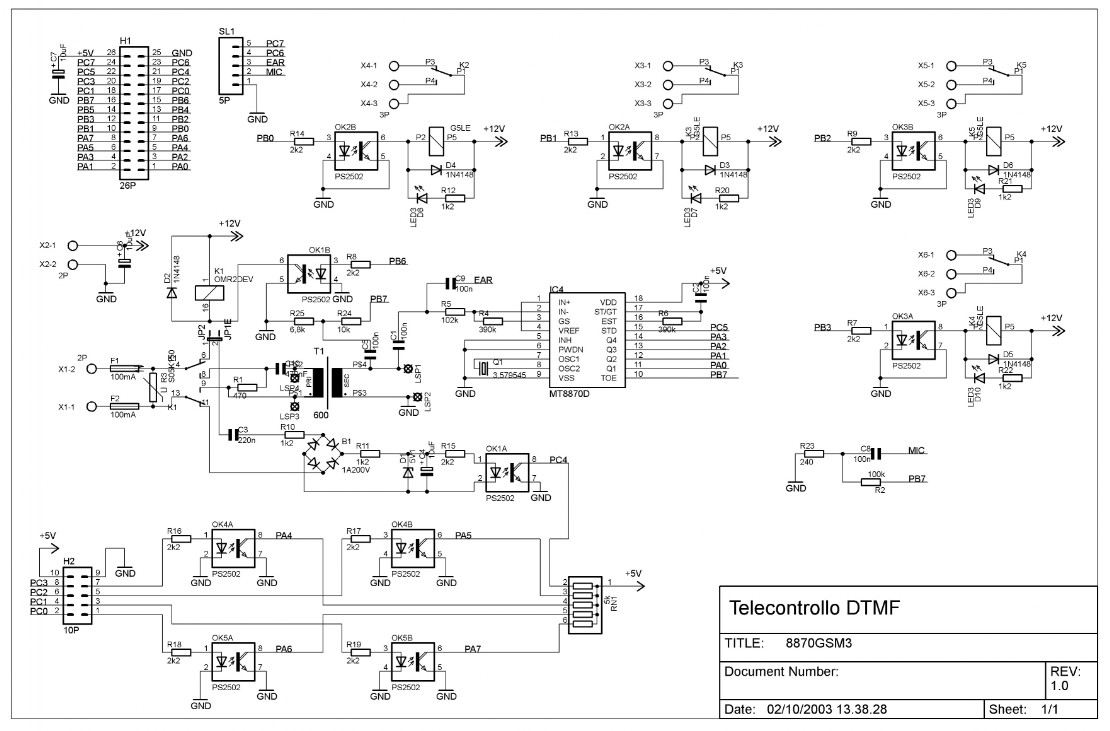
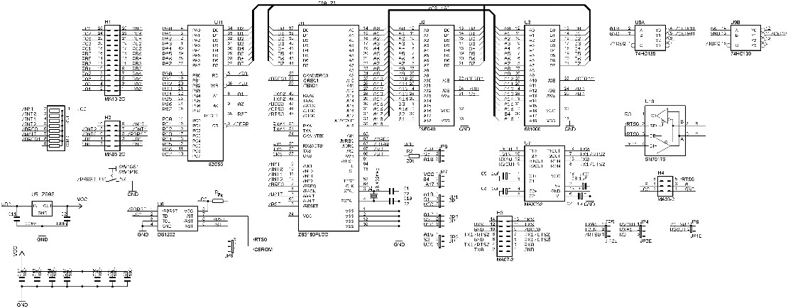
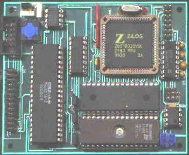
- Hardware: ELC-180 NVRAM CPU + ELC-8870 interface
- Software: Management program resident on 32k EPROM
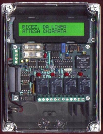
- Container: IP65 polycarbonate with transparent cover
- Power supply: 12VDC 400 mA
- Indications: 2 line x 20 character LED illuminated LCD, 4 output relay status LEDs
- Switching: From fixed line to automatic GSM
- Telephone interface: Line isolation transformer, varistors and fuses against transient overvoltages.
- GSM interface: Audio, (headset microphone)
- Audio input levels: 20mV to 900mV
- Audio output level: 10mV
- GSM connector: 3 lines IN, OUT, GND
- Output relays: 4 10A 250V SPST relay switches with optocouplers
- Output connectors: 12-pole internal screw terminal block (4 x COM, NO, NC)
- Auxiliary inputs: 1 10-pole connector 4 TTL 0 - 5V level inputs, 1 5-pole connector for connection to a GSM mobile phone.
- Serial interface: 1 RS232C port (internal conn.)
- Dimensions: 175 x 125 x 75 mm
- Automatic switching from GSM to telephone line; the remote control recognizes the insertion of the SL1 connector relative to the mobile phone, by testing pin 5 of the connector (green); in particular if this pin is connected to ground, the DTMF reception from the mobile phone is activated; if pin 5 is free, reception from the telephone line is enabled.
- Possibility of connecting the LCD module, by means of a special cable; the display shows information relating to the various execution steps of the management program.
- Availability of a line for manual control of the relays; if pin 4 (red) of the SL1 connector is connected to ground via a NO button, it is possible to perform a cyclical activation-deactivation, with a period of 1 s of all relays, useful for local checks or activation-deactivations of the devices connected to the relays.