Industrial GSM remote alarm
Sentinel SMS industrial remote alarm for automatic milling machines
General description
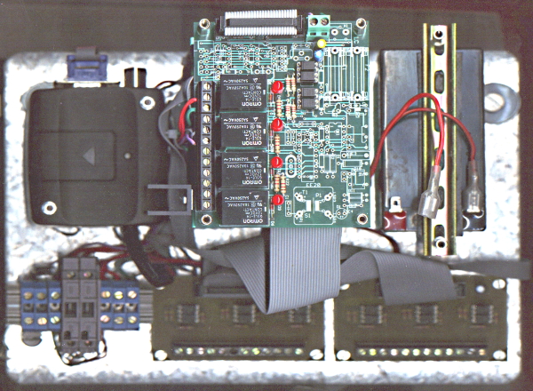
The SENTINEL SMS remote alarm performs the function of sending SMS messages on the GSM network associated with the status of 11 optoisolated inputs which analyze the logic level of as many signals sent by MECOF machine tools. The SENTINEL, in the KIT version, is assembled on a galvanized steel plate with dimensions 199 x 235 x 1.5 mm equipped with brackets for mounting on a 35 mm symmetrical DIN rail and consists of the following hardware modules:
- CPU CARD ELC-180 V.2-3 128k EPROM 32k NVRAM clock 18.432 MHZ
- ELC-8870 OEM RELAY BOARD with 4 RELAYS + 4 signaling LEDs
- LINEAR REGULATOR CARD ELC-350/24 IN 24VDC OUT 13,8VDC 2A
- GSM MODEM DUAL BAND 900/1800 MHz AT support GSM07.07 and 07.05
- OPTO-ISOLATED INPUT CARDS ELC-180IO
- LEAD ACCUMULATOR 12VDC 1,2 AH
- DUAL BAND 900/1800 MHz ANTENNA WITH MAGNETIC BASE
The system has a linear power supply-regulator which not only supplies the boards and the MODEM, but also the maintenance charge of a 12V accumulator connected in buffer to guarantee operation even in the temporary absence of the main power supply on the 24V line; autonomy is about 3 hours in ST-BY. The SENTINEL monitors 12 digital input lines (I0 ..... I11), connected to the MECOF machine tool. The standard type of operation foresees the following signal levels at the SENTINEL input:
The first line I0 is normally at logic level 1 (Vin = 24V) and if it is brought to level 0, it causes a reset of the SMS transmission memories.
The other 11 lines (I1 ...... I11) must normally be at logic level 1 (Vin = 24V); each line if brought to logic level 0 (Vin = 0V) determines the transmission of the SMS associated with that line, to all users (from 1 to 10) memorized during the setup phase, relative to that line. Once the SMS of a line has been sent to the respective recipients, a transmission memory flag associated with that line is set to avoid repetition of the transmission: each SMS can therefore be sent only once, to all recipients. expected.
To re-enable the lines to send an SMS again, it is necessary to reset the transmission memory, bringing the I0 line to level 0. Line I11 also performs the function of enabling entry into the setup, as described in paragraph 2.
The GSM MODEM is normally off, and is turned on only after the request for sending SMS, and then goes off again, once the SMS transmission phase is completed. The parameters and data entered by the user during the setup phase are stored on the main non-volatile memory (NVRAM) of the CPU board. The operating states of the SENTINEL are signaled by 4 LEDs which indicate respectively: the power on / initialisation, the reset, the MODEM power on and the sending of SMS.
Installation and Setup
The SENTINEL can be mounted inside a cabinet on symmetrical DIN rails, using the 4 built-in hooks. Forced ventilation is not required, unless the level of convection heat exchange inside the cabinet is insufficient, due to a too small volume or a high degree of watertight protection, in which case it is advisable to install a small axial fan.
It is then necessary to carry out the following operations:
Connect an external key switch to terminals 7 and 8 of the DIN terminal block, for general ignition. The switch does not control the recharging of the accumulator, which is always active, but only the switching on of the SENTINEL.
Connect the Faston of the positive power supply pole to the battery (disconnected during the transport and storage phases), checking the state of charge of the same by the green LED on the power supply board.
Connect the logic signal lines (0 - 24V) to the optoisolated input terminal block, according to the attached diagram, connecting the respective GROUND line for each input.
Connect the 24VDC power source to terminals 1 and 2 of the DIN terminal block. The power supply voltage must not exceed 24 VDC and must be included in the range 18 .... 24 VDC. The maximum current absorbed by the Sentinel on the 24V line is approximately 400 mA.
Connect a PC equipped with a terminal emulation program (eg PROCOMM, Hyperterminal, etc.) to the serial cable of the RS-232C port.
Switch on the SENTINEL using the key switch. At this point, the following 2 situations can occur:
If line I11 is at level 0V or open, you enter the setup phase; you can enter the desired parameters, the text of the SMS and the numbers of the recipients: once this operation has been completed, you can exit the setup menu and enter the normal operating mode.
If line I11 is at + 24V level, you enter the operating phase directly and if it has been enabled in setup, line I11 is also associated, like the other ten, with the sending of an SMS in the event of a change in status from + 24V to 0V. Line I11 therefore has a double function, it controls both the start-up of the setup in the power-up phase and the sending of the associated SMS during the subsequent phase of normal operation. During normal operation, line I11 must therefore always be kept at the + 24V level, even if it has not been enabled, in order to return to normal operating mode in the event of a Sentinel switching off and on or hardware RESET.
Antenna positioning and orientation
If, before switching on the SENTINEL, the I0 line is brought to level 0, in addition to resetting the transmission memory, the MODEM is switched on and a test loop of the RF signal is accessed, with continuous display of the level of signal and Bit Error Rate (BER), useful for determining the optimal position and orientation of the MODEM external antenna. The received field intensity is expressed in [dBm] and the indication can vary in the range from -113 dBm (no or very weak field) to -51 dBm (very strong field). The minimum field intensity threshold necessary for the correct functioning of the Sentinel is -93 dBm. The BER is expressed as a percentage and the maximum allowed threshold is 0.2% Once this phase is completed, the I0 line can be brought back to logic level 1 (Vin = 24V), thus returning to the normal operating mode. .
Precautions and warnings
When the Sentinel is not used, or is expected to remain inactive for a long time without the 24V power supply, it is necessary to disconnect the faston of the positive terminal of the accumulator, to avoid its complete discharge. On the DIN terminal board there are 2 5x20 mm 1A protection fuses on the 24 V input line and on the regulator output line.
TECHNICAL FEATURES
- Hardware: ELC-180V2-3 + ELC-8870OEM + ELC35024V + ELC180IO6
- Software: SENTINEL REL2.01 operating program on 64k x 8 EPROM
- Inputs: 12 optoisolated inputs (optodarlington) 5000V isolation
- Signal levels: V in = 0: logic level = 0; Vin = 24VDC: logic level = 1
- SMS messages: Up to 11 SMS, maximum size 80 characters
- Num. Recipients: Up to 10 recipients per entry, maximum size 20 digits
- User setup: PC setup for the number of enabled inputs, SMS and recipients.
- Output relays: 4 optoisolated 10A 250V single pole relay switches
- Serial ports: 2 RS232C, 1 of which is used by the GSM MODEM
- Power supply: Linear regulator IN = 18 ..... 24 VDC, OUT = 13,8VDC 2A
- Signals: 4 red LEDs for: power on, reset, MODEM ON, send SMS
- 1 green LED for 24VDC input and / or accumulator.
- Autonomy: About 3 hours in ST-BY with integrated 12VDC 1,2Ah battery
- Protections: 1 fuse 1A 24V input; 1 fuse 1A regulator output
- Support: Galvanized steel plate 199 x 235 x 1.5 mm
- Dimensions: Overall dimensions 199 x 235 x 95 mm
- Weight: 2.1 Kg